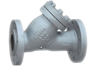
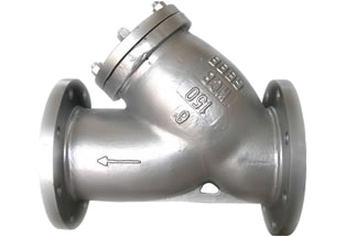
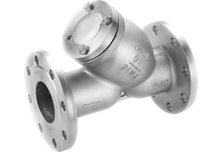
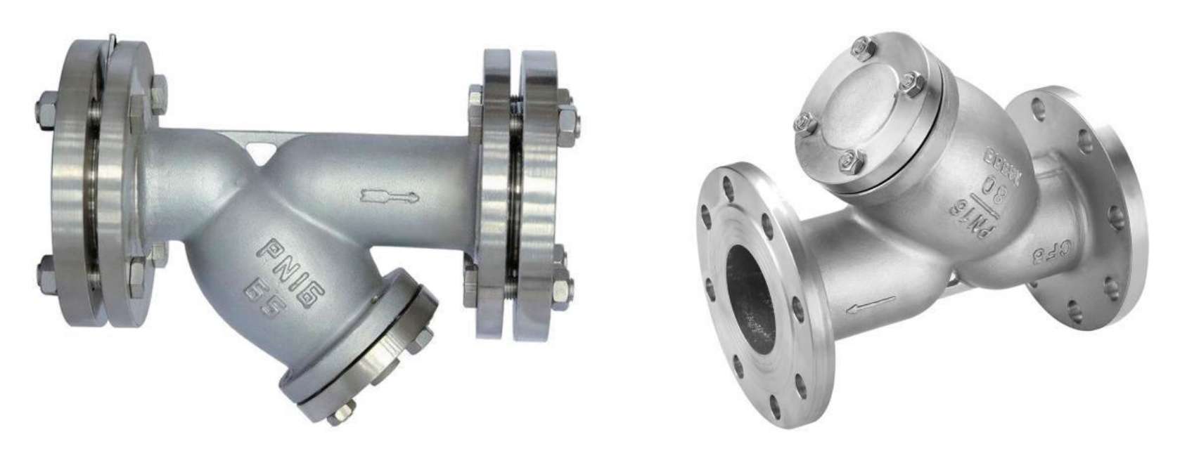
ANSI Steel Flanged Y Strainer
150LB / 300LB
1/2″~24″ (15~600mm)
A216 WCB, A351 CF8, CF8M
get a quote
ANSI Steel Flanged Y Strainer Descriptions
ANSI steel flanged Y Strainer is one type of device for mechanically removing unwanted solids from liquids, gas or steam lines by means of a perforated or wire mesh straining element. ANSI Y strainer is used in pipelines to protect pumps, meters, control valves, steam traps, regulators and other process equipment. Flowspec Luokai can produce and supply the ANSI steel flanged Y strianer according to ASME B16.34 with class rating 150LB and 300LB. Just feel free to contact us now to get best prices. 30 years of experience. High quality. Big stock. Fast delivery.
1. FEATURES
- Advanced structure
- Small resistance
- Easy draining
- Mesh 18-30 for water pipeline
- Mesh 10-100 for gas pipeline
- Mesh 100-480 for oil pipeline
3. STANDARDS
- Design & manufacturing: ASME B16.34
- Face to face: ANSI B16.10
- Flanged ends: ANSI B16.5
- Inspection & testing: API598
2. TECHNICAL SPECIFICATIONS
- 150LB / 300LB
- Size: 1/2″~24″ (DN15~DN600mm)
- Materials: carbon steel A216 WCB, stainless steel 304 (CF8), stainless steel 316 (CF8M)
- Applicable medium: water, oil, gas
- Applicable temperature: ≤300℃ (higher temperature is available upon request)
4. APPLICATIONS
- Water works, water projects
- Environment protection
- Public facilities
- Power plant
- Building industry, real estate
- Petroleum, chemical industry
- Steel work, metallurgy
- Food & beverage
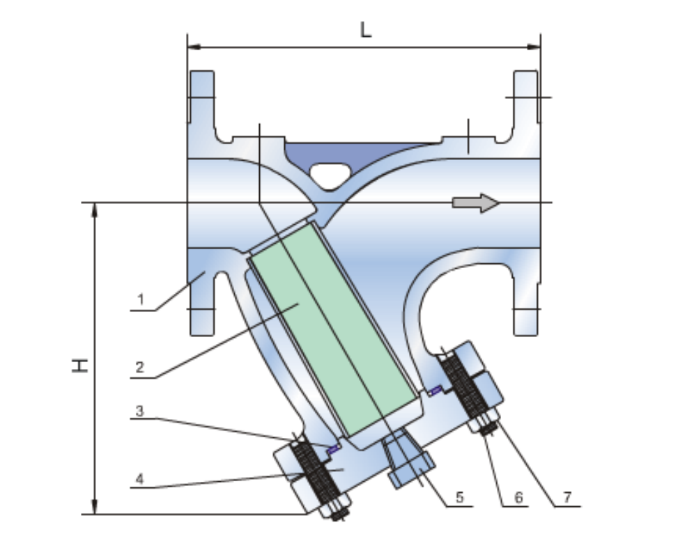
| ITEM | PART NAME | MATERIAL | |||||
|---|---|---|---|---|---|---|---|
| 1 | Body | ASTM A216 GR.WCB, A351 CF8 (S.S.304), A351 CF8M (S.S.316) | |||||
| 2 | Screen | ASTM A276 Type 304 | |||||
| 3 | Gasket | 304+Graphite, 316+Graphite | |||||
| 4 | Cover | ASTM A216 GR.WCB, A351 CF8 (S.S.304), A351 CF8M (S.S.316) | |||||
| 5 | Plug | ASTM A105, S.S.304, S.S.316 | |||||
| 6 | Cover Bolts | ASTM A193 GR.B7, A193-B8, B8M | |||||
| 7 | Cover Bolt Nuts | ASTM A194 GR.2H, 8, 8M | |||||
| MAIN CONNECTION DIMENSIONS 150LB | |||||||
| Size | L | H | D | D1 | D2 | N-d | |
| in | mm | mm | mm | mm | mm | mm | mm |
| 1/2” | 15 | 142 | 80 | 89 | 60.5 | 35 | 4-15 |
| 3/4” | 20 | 142 | 87 | 98 | 70 | 43 | 4-15 |
| 1” | 32 | 160 | 92 | 108 | 79.5 | 51 | 4-15 |
| 1-1/4” | 40 | 180 | 105 | 117 | 89 | 64 | 4-15 |
| 1-1/2” | 50 | 200 | 117 | 127 | 98.5 | 73 | 4-15 |
| 2″ | 50 | 203 | 145 | 152 | 120.5 | 92 | 4-19 |
| 2.5″ | 65 | 216 | 183 | 178 | 139.5 | 105 | 4-19 |
| 3″ | 80 | 241 | 206 | 190 | 152.5 | 127 | 4-19 |
| 4″ | 100 | 292 | 228 | 229 | 190.5 | 157 | 8-19 |
| 6″ | 150 | 406 | 329 | 279 | 241.5 | 216 | 8-22 |
| 8″ | 200 | 495 | 440 | 343 | 298.5 | 270 | 8-22 |
| 10″ | 250 | 622 | 507 | 406 | 362 | 324 | 12-25 |
| 12″ | 300 | 699 | 594 | 483 | 432 | 381 | 12-25 |
| 14 | 350 | 787 | 614 | 535 | 476 | 413 | 12-29.5 |
| 16 | 400 | 914 | 635 | 600 | 540 | 470 | 16-29.5 |
| 18 | 450 | 978 | 693 | 635 | 578 | 533.5 | 16-32.5 |
| 20 | 500 | 978 | 765 | 700 | 635 | 584 | 20-32.5 |
| 24 | 600 | 1295 | 894 | 815 | 749.5 | 692 | 20-32.5 |
| MAIN CONNECTION DIMENSIONS 300LB | |||||||
| Size | L | H | D | D1 | D2 | N-d | |
| in | mm | mm | mm | mm | mm | mm | mm |
| 1/2” | 15 | 165 | 80 | 95 | 66.5 | 35 | 4-15 |
| 3/4” | 20 | 165 | 87 | 117 | 82.5 | 43 | 4-19 |
| 1” | 32 | 190 | 92 | 124 | 89 | 51 | 4-19 |
| 1-1/4” | 40 | 190 | 105 | 133 | 98.5 | 64 | 4-19 |
| 1-1/2” | 50 | 229 | 117 | 156 | 114.5 | 73 | 4-19 |
| 2″ | 50 | 267 | 145 | 165 | 127 | 92 | 4-19 |
| 2.5″ | 65 | 292 | 183 | 190 | 149 | 105 | 8-19 |
| 3″ | 80 | 318 | 206 | 210 | 168.5 | 127 | 8-22 |
| 4″ | 100 | 356 | 228 | 254 | 200 | 157 | 8-22 |
| 6″ | 150 | 445 | 329 | 318 | 270 | 216 | 12-22 |
| 8″ | 200 | 559 | 440 | 381 | 330 | 270 | 12-25 |
| 10″ | 250 | 622 | 507 | 444 | 387.5 | 324 | 16-29.5 |
| 12″ | 300 | 711 | 594 | 521 | 451 | 381 | 16-32 |
| NOTES: As we are constant endeavoring to improve the performance of our equipment. |
|||||||
| The company reserves the right to make alteration from time to time and equipment differ from that detailed in this brochure. |
|||||||