sales@lokvalve.com

How to install an electric ball valve
 secureluokai
 November 12, 2026
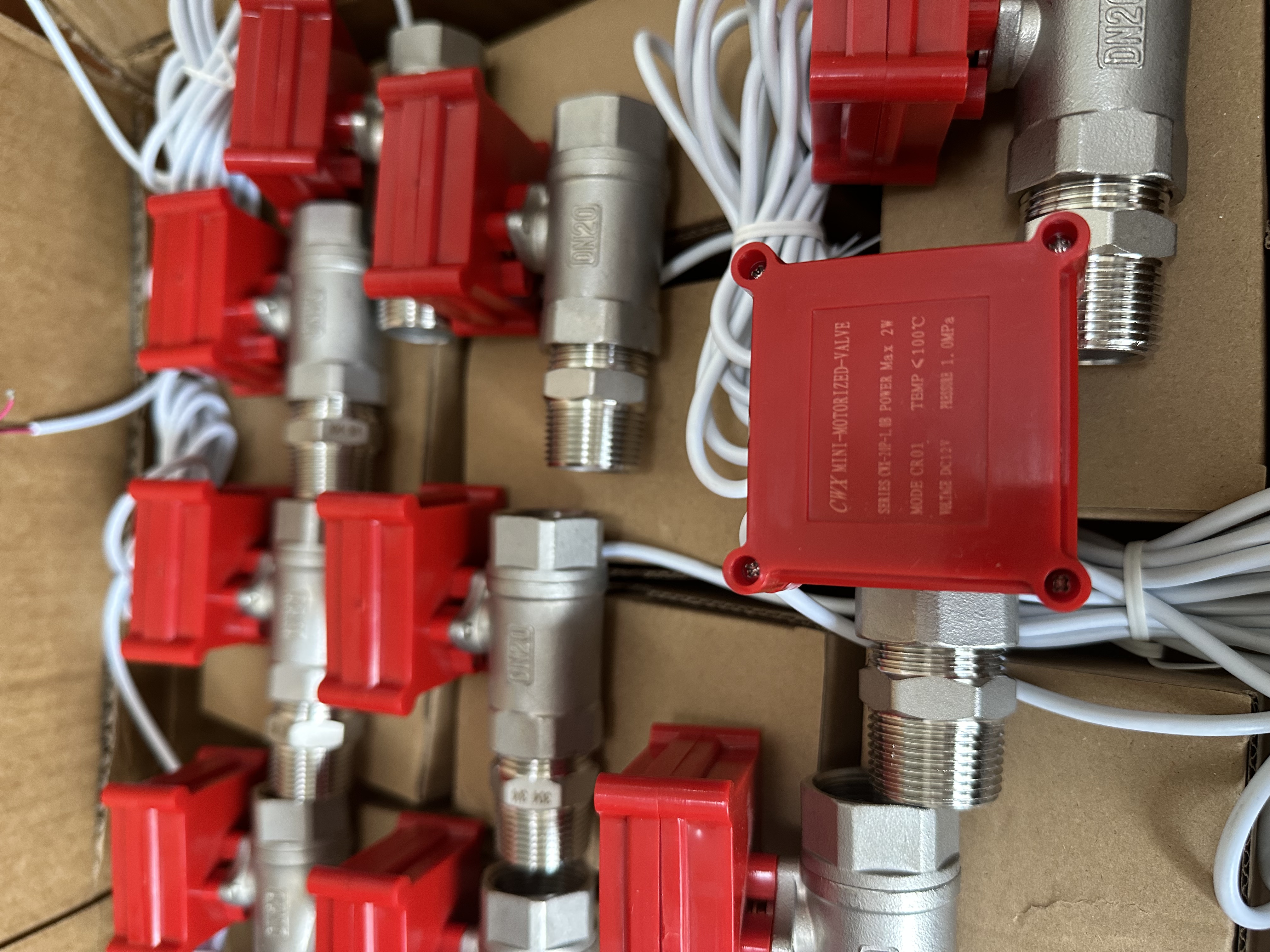
Installing an electric ball valve correctly helps ensure reliable flow control, tight shutoff, and dependable operation in water treatment systems, heating and cooling networks, and industrial process lines. An electric ball valve combines a ball valve body with an electric actuator, which rotates the ball to open, close, or regulate the flow. Although installation may appear straightforward, the work involves mechanical connections, electrical wiring, and functional testing. Errors such as misaligned pipework, incorrect supply voltage, or improperly adjusted travel limits can cause leakage, equipment damage, or operational failure. The correct procedure depends on the valve design, connection type, actuator specifications, and operating conditions. Always use the manufacturer’s installation instructions as the primary reference, and have electrical connections completed by personnel qualified for the equipment and applicable local requirements.
Before installation, confirm that the complete valve assembly is suitable for the application. Check the nominal pipe size, pressure and temperature ratings, body material, seat material, and compatibility with the process fluid. Verify the actuator’s supply voltage, control signal, enclosure rating, and duty cycle against the system requirements. A valve intended for occasional isolation may not be suitable for frequent cycling or continuous modulation. Also confirm the required behavior during a power failure: many standard electric actuators remain in their last position, while specific designs use springs or stored electrical energy to move to a designated safe position. Isolate the relevant pipe section, release pressure, drain it, and allow hot components to cool before work begins. Apply the site’s energy isolation procedure to prevent accidental operation. Inspect the valve for shipping damage and remove protective packaging or port covers. Flush or clean the pipework to remove welding debris, grit, and other contaminants that could damage the seats. Prepare suitable gaskets, fasteners, sealing materials, supports, and tools before placing the valve in position.
For mechanical installation, choose an accessible location with enough clearance for wiring, manual operation, inspection, and future removal. Follow the manufacturer’s permitted mounting orientations; many assemblies are installed with the actuator above the pipe, but allowable positions vary. Avoid locations where the actuator could become submerged or where its temperature limits could be exceeded. Support and align the pipework independently so that the valve does not carry excessive pipe weight or bending loads. Check for a flow arrow or other orientation markings. Many ball valves allow flow in either direction, but some designs have directional requirements because of their seats, cavity relief arrangements, or intended service. For threaded connections, use a compatible thread sealant sparingly and prevent it from entering the flow passage. Apply a wrench to the appropriate flats near the connection being tightened, and never use the actuator as a lever. For flanged valves, check flange alignment, select the specified gasket type, and tighten bolts progressively in a cross pattern to the required torque. Welded connections require the manufacturer’s specific procedure to protect seats, seals, and the actuator from heat; certain designs require disassembly before welding. Keep the ball in the position specified for the installation method, and ensure that gaskets or pipe ends do not obstruct its movement.
Complete the electrical installation only after the mechanical assembly is secure and the electrical supply is isolated. Read the wiring diagram supplied with the exact actuator model, since similar housings can contain different voltage options and control arrangements. Common configurations include simple open-and-close control, three-point floating control, and modulating control using signals such as 4–20 mA or 0–10 V. These arrangements are not interchangeable, and terminals for power, commands, and position feedback must be identified correctly. Check the required protective device, cable size, protective earth connection where applicable, and any specified disconnecting means. Use cable glands and seals suitable for the enclosure rating, cable diameter, and installation environment. Route cables to reduce strain and prevent water from tracking into the housing. Follow the manufacturer’s guidance on separating signal wiring from power wiring and terminating cable shields. Where an actuator includes a manual override, use it only according to its instructions; some mechanisms require power isolation or disengagement before manual movement. Factory settings for travel limits, mechanical stops, and torque protection should be verified during commissioning and adjusted only when the manufacturer’s procedure requires it.
Commission the electric ball valve through controlled mechanical, electrical, and process checks. Before filling the line, confirm that fasteners are secure, wiring is correct, and tools or loose materials have been removed. If permitted by the manufacturer, operate the valve without process pressure to check smooth travel and agreement between the actual ball position and the actuator indicator. Apply power and command a complete opening and closing cycle, verifying the direction of movement, stopping positions, and feedback signals. For a modulating valve, check intermediate commands and perform any required calibration. Reintroduce the process fluid gradually, vent trapped air where appropriate, and inspect all connections for leakage. Conduct pressure and seat leakage tests using an approved procedure within the assembly’s specified limits; avoid exposing the valve or actuator to unapproved test conditions. Under normal operating conditions, watch for abnormal noise, vibration, overheating, or failure to reach the commanded position. Test the specified response to loss of power or control signal where this can be done safely. Record the wiring details, settings, test results, and maintenance requirements so that future inspections and troubleshooting can be completed efficiently.
If you have any questions or inquiries, please feel free to contact us with sales@lokvalve.com or WhatsApp: +8618616568786