Pneumatic Cage Guided Globe Control Valve
PN16~PN64
DN32~DN200mm
Steel, S.S.304, S.S.316
get a quote
Pneumatic Cage Guided Globe Control Valve Product Information
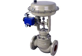
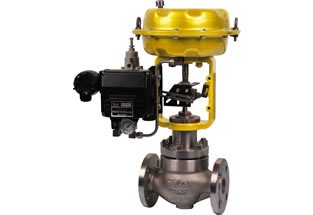
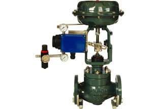
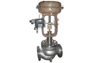
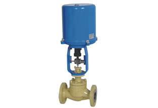
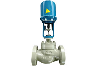
Pneumatic cage guided globe control valve is one type of pressure balance regulating valve with pneumatic diaphragm actuator, whose valve flow port is s-shaped linear type. It has a contra-vane to improve the fluids flow balance arounds the cage. Cage type globe control valve is normally used to control high pressure fluids, because it’s featured with small pressure drop, big flow capacity, wide adjustable range and high flow characteristic accuracy. Its actuator can be pneumatic diaphragm type or electronic electric actuator. Flowspec Luokai can manufacture and supply the Pneumatic cage guided globe control valve with sizes of 1-1/4″ ~ 8″ (DN32~DN200mm). Contact us today. Get the better prices. 30 years of experience. Great after-sales service.
1. FEATURES
- S shaped flow port, linear flow characteristic.
- Small pressure drop loss, big flow capacity.
- Compact structure, wide adjustable range.
- Small noise, little cavitation corrosion.
- Excellent regulation performance, accurate flow coefficient.
3. STANDARDS
- Design & manufacturing: GB/T 12221-2005
- Flanged ends: GB/T 9113.1-2000, ANSI 16.5, JIS B2201
- Face to face: GB/T 12221-2005
- Inspection & testing: GB/T 13927-2000
2. TECHNICAL SPECIFICATIONS
- PN1.6~PN6.4Mpa, Class 150LB, 300LB, 600LB, JIS 10K, 16K, 20K
- Size: 1-1/4″ ~ 8″ (DN32~DN200mm)
- Materials: carbon steel (WCB), stainless steel 304(CF8), stainless steel 316(CF8M)
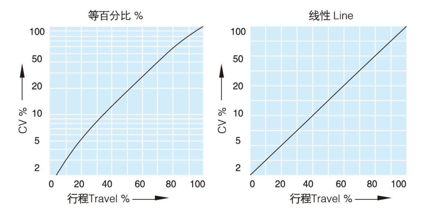
- Flow characteristic: linear, equal percentage
- Intrinsic error: <±1%
- Hysteresis:<±1%
- Cv ratio: 50:1
- Leakage class: ANSI B16.104 class IV, class VI, class II
- Applicable medium: water, oil, gas, corrosive liquids
- Applicable temperature: -17℃~230℃ (higher temperature is available upon request)
4. APPLICATIONS
- Power plant
- Pharmaceutical factory
- Chemical industry
- Water plant
- Steel plant
- Metallurgy
| 驱动方式 Driving Mode |
电动、气动(1.4~4bar) Electric, Pneumatic | |||
|---|---|---|---|---|
| 公称通径 DN | 32~200mm | |||
| 公称压力 PN | 1.6~6.4MPa | |||
| 适用温度 Applicable Temp. |
PTFE & FEP(F46): | -17~+100℃ | 低温型 Low temp.type |
-196~+100℃ |
| 高温型 High temp.type |
-17~+566℃ | 常温型 Normal temp.ptype |
-17-+230℃ | |
| 流量特性 Flow characteristics |
线性Line、等百分比% | |||
| 回差 Hysteresis errors |
小于全行程的1% Less than 1% of the whole travel | |||
| 基本误差 Intrinsic errors |
小于全行程的±1% Less than ±1% of the whole travel | |||
| 可调范围 Adjustable range |
50:1 | |||
| 可选附件 Optional | 定位器、电磁阀、过滤调压阀、手轮 Positioner, Solenoid valve, Air filter regulator, Handwheel |
|||
| 流量系数 The flow coefficient | |||||||||||||
|---|---|---|---|---|---|---|---|---|---|---|---|---|---|
| 公称通径DN | 20 | 25 | 32 | 40 | 50 | 65 | 80 | 100 | 150 | 200 | |||
| 阀芯Core | 25/32 | 25/32/50 | 32/40/50 | 40/50/65 | 50/65/80 | 65/80/100 | 100/125/150 | 125/150/200 | |||||
| CV | 0.01-10 | 0.01-14 | 10/17 | 10/17/24 | 17/27/44 | 24/44/68 | 44/68/99 | 68/99/175 | 175/275/360 | 275/360/640 | |||
| 行程 Travel | 14.3 | 14.3 | 25 | 25 | 25 | 38 | 38 | 38 | 50 | 75 | |||
| 压差范围 Differential pressure range Unit:100KPa | |||||||||||||
| 出厂状态Failure position | 供气压力 Air supply pressure |
弹簧范围Spring range | 压差范围 Differential pressure range 阀芯Core |
||||||||||
| 20 | 25 | 32 | 40 | 50 | 65 | 80 | 100 | 125 | 150 | 200 | |||
| 开启 Open |
1.4 | 0.2-1.0 | 20-40/100 40/100 40/100 20-40/100 40/100 |
9.9 | 7.7 | 11.7 | 9.7 | 7.4 | 6.3 | 5.2 | 7.4 | ||
| 1.6 | 0.2-1.0 | 40/49.2 | 38 | 40/58 | 40/48.7 | 37 | 31 | 26.1 | 37 | ||||
| 4.0 | 0.8-2.4 | 40/100 | 40/100 | 40/100 | 40/100 | 40/100 | 40/89 | 40/78.6 | 40/100 | ||||
| 关闭 Close |
1.4 | 0.2-1.0 | 9.9 | 7.7 | 11.7 | 9.7 | 7.4 | 6 | 5.2 | 7.4 | |||
| 2.8 | 0.8-2.4 | 40/68.1 | 40/53.9 | 40/81.7 | 40/68 | 40/51.8 | 40/44 | 36.7 | 40/51 | ||||
备注 Note:1、最大允许压差不超过最大工作压力
The maximum allowable differential pressure does not exceed the maximum pressure
2、同一格内,/前方数字表示阀常开允许压差,后方数字表示阀全关允许压差。
The number in the front of ‘/ ‘indicates the allowable differential pressure for valv e totally opened, the rear numerals indicates the allowable differential pressure for valve
totally closed.
3、以上允许压差均采用标准执行机构,当压差不满足时,也可增大执行机构。
The above allowable differential pressure under standard actuator, If the differential pressure is not enough then can use enlarged actuator.
此阀设有一个改善套筒周围流体平衡流动的导流翼,是控制高压流体的阀门,是一种压力平衡式调节阀。有压降小,流量大,可调范围广,流量特性精度高的特点。执行器可采用气动薄膜式、电子式电动执行机构,出厂时已经将零点量程调试完毕,用户接通气源输入信号即可运转使用。
The valve has a turning vane improving the sleeve surrounding fluid flow balance, and is a highpressure fluid control valve, and is a kind of pressure balance type regulator. It has the characteristicsof small pressure drop, large flow, wide adjustable range, and flow characteristic of high precision.Actuator can adopt pneumatic diaphragm and electronic electric actuator. When delivery, zero rangehas been debugge
d. After the user switches on air input signal, it can operated and be used.
※ 接线简单,操作简易。
Wiring is simple, easy to operate.
※ 调节性能优异,流量系数精确。
Regulation performance is excellent, flow coefficient is accurate.
※ 通道呈S型,压力损失小,流通能力强。
The channel is S type. Pressure loss is low, circulation ability is strong.
※ 有一定黏度和少量纤维的介质也可以选用。
It can be applied to medium with viscosity and a small amount of fiber.
cage guided control valve
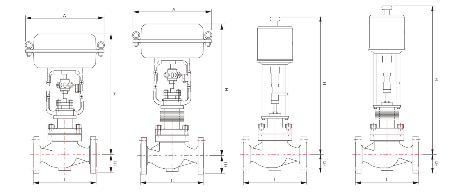
| 气动薄膜套筒调节阀外形尺寸The dimension of pneumatic diaphragm cage guided control valve Unlt:mm | |||||||||
|---|---|---|---|---|---|---|---|---|---|
| SIZE | 执行器Actuator | H | H1 | A | |||||
| 常温 Normal temp. |
高温| High temp. |
高温Ⅱ High temp. |
高温Ⅲ High temp. |
||||||
| 32 | 1-1/4″ | ZHA2R/D | 500 | 665 | 780 | 1020 | 70 | 281 | |
| 40 | 1-1/2″ | ZHA2R/D | 500 | 665 | 780 | 1020 | 70 | 281 | |
| 50 | 2″ | ZHA2R/D | 500 | 670 | 785 | 1025 | 80 | 281 | |
| 65 | 2-1/2″ | ZHA3R/D | 630 | 800 | 930 | 1180 | 88 | 363 | |
| 80 | 3″ | ZHA3R/D | 635 | 810 | 955 | 1190 | 98 | 363 | |
| 100 | 4″ | ZHA3R/D | 660 | 860 | 1020 | 1205 | 113 | 363 | |
| 125 | 5″ | ZHA3R/D | 785 | 1020 | 1250 | 1385 | 170 | 363 | |
| 150 | 6″ | ZHA3R/D | 785 | 1020 | 1250 | 1385 | 170 | 363 | |
| 200 | 8″ | ZHA4R/D | 1090 | 1350 | 1580 | 1710 | 220 | 520 | |
| 备注: R气开式 D 气闭式 Remarks:R for air to opne D for air to close H栏尺寸不包含手轮、定位器、加大执行器尺寸The dimension of H does not contain a hand wheel, positioner, enlarged actuator |
|||||||||
| 电子式电动套筒调节阀外形尺寸 The dimension of electric cage guided control valve Unlt:mm | |||||||||
| SIZE | 执行器Actuator | H | H1 | ||||||
| 常温Normal temp. | 高温 High temp. | ||||||||
| 32 | 1-1/4″ | LFL-204 | 771 | 922 | 70 | ||||
| 40 | 1-1/2″ | LFL-204 | 771 | 922 | 70 | ||||
| 50 | 2″ | LFL-204 | 801 | 952 | 80 | ||||
| 65 | 2-1/2″ | LFL-208 | 910 | 1060 | 88 | ||||
| 80 | 3″ | LFL-208 | 926 | 1077 | 98 | ||||
| 100 | 4″ | LFL-210 | 934 | 1085 | 113 | ||||
| 125 | 5″ | LFL-312 | 1133 | 1348 | 170 | ||||
| 150 | 6″ | LFL-312 | 1133 | 1348 | 170 | ||||
| 200 | 8″ | LFL-314 | 1216 | 1431 | 220 | ||||
| L:阀体长度 Body length Unit:mm | |||||||||
| SIZE | ANSI 125 FF | JIS 16K RF | ANSI 300 RF | ANSI 600 RF | JIS 16K | JIS 20K | JIS 30K | JIS 40K | |
| ANSI 150 RF | JIS 20/30K RF | JIS 40K RF | 沟槽Groove | ||||||
| JIS 10K FF RF | JIS 30K RF | PN64 | 嵌入Embedding | ||||||
| PN16 RF | PN40 RF | ||||||||
| DN32 | 1-1/4″ | 200 | / | / | / | / | / | / | / |
| DN40 | 1-1/2″ | 222 | 231 | 235 | 251 | 235 | 236 | 248 | 251 |
| DN50 | 2″ | 254 | 263 | 267 | 286 | 265 | 267 | 276 | 286 |
| DN65 | 2-1/2″ | 276 | 288 | 292 | 311 | 290 | 292 | 303 | 311 |
| DN80 | 3″ | 298 | 313 | 317 | 337 | 310 | 317 | 326 | 337 |
| DN100 | 4″ | 352 | 364 | 368 | 394 | 360 | 368 | 378 | 394 |
| DN125 | 5″ | 410 | / | / | / | / | / | / | / |
| DN150 | 6″ | 451 | 465 | 473 | 508 | 475 | 473 | 486 | 508 |
| DN200 | 8″ | 543 | 560 | 568 | 610 | 570 | 568 | 580 | 610 |