Bronze Wafer Check Valve Product Information
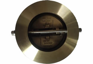
Bronze wafer check valve is one type of wafer dual plate check valve, which can be mounted on the piping end as exhaust valve.Wafer type dual plate check valve is with two torsion springs added to each of pair valve plates, which close the plates quickly and automatically, that can prevent the medium from flowing back. The check valve can be mounted onto both horizontal and vertical direction pipelines. Flowspec Luokai can manufacture the bronze wafer check valve according to standard of ASME B16.34 / API594 with sizes of 2″~60″ (DN50~1500mm). Just feel free to contact us now to get best prices. 30 years of experience. High quality. Big stock. Fast delivery.
1. FEATURES
- Small in size, light weight, compact structure, easy maintenance
- The quick action prevents of medium back flow
- Short face to face and good rigidity
- Easy installation, can be mounted horizontally and vertically
- This valve is tightly sealed, without leakage
- Safe and reliable operation, high interference-resistance
3. STANDARDS
- Design & manufacturing: ASME B16.34 / API594
- Face to face: API594
- Matching flanges: ANSI B16.5 RF
- Inspection & testing: API598
2. TECHNICAL SPECIFICATIONS
- 150LB/300LB/600LB/900LB
- Size: 2″~60″ (DN50~1500mm)
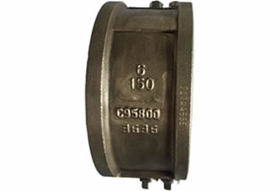
- Materials: bronze B148 C95500, C95400, C95800, C95200, C92200, C83600, C84400, C90500
- Applicable medium: water, sewage, sea water, air, steam, gas, oil
- Applicable temperature: ≤+250℃ (higher temperature is available upon request)
4. APPLICATIONS
- Oil & gas field
- Environment protection
- Marine service
- Power plant
- Sea water desalination
- Offshore project
- Steel work, metallurgy
Dusl plste wsfer check vslve has a shorter face-to-face
dimension and dual plate design, the end connection
options Include wafer type, lug type and double-flange type,
and are available In size from 2″ to 60″ and I n pressure
ratings from ASME class 150 through 2500. A wide range of
body and trim msterisls are optionsion customer’s request.
Compared to coventional swing check valves, NEWAY’S
dual plate check valves have the advantage of zero leakage
toward outside (no bolted or threaded connections), cost
savings, they can be installed in any line orientation,
superlor seal performance, offer mInImal line shock, lower
pressure loss and zero seat wear.
This series of valves are widely used in oil & gas production,
petroleum reflning, petrochemlcal, pulp & paper,
shipbullding, and other f luld back flow prevention
application.
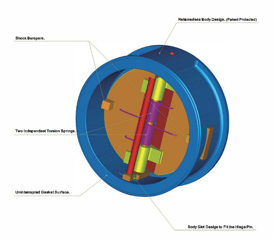
Shock Bumpers.
Two Independent Torsion Springs.
Retainerless Body Design.(Patent Protected)
Uninterrupted Gasket Surface.
Body Slot Design to Fit the Hinge Pin.
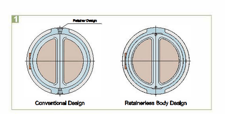
1 Retainerless Body Design (Patant Protactad)
Dual plate valve bodles are a one-piece and short cyllnderdesign with no holes through body wall, there is no need for externalpins or plugs and no leakage towardoutskdFor criticalservice applications, such as hazardous or poisonous medium, thisis a superior choice to minimize unwanted leakage to atmosphere.
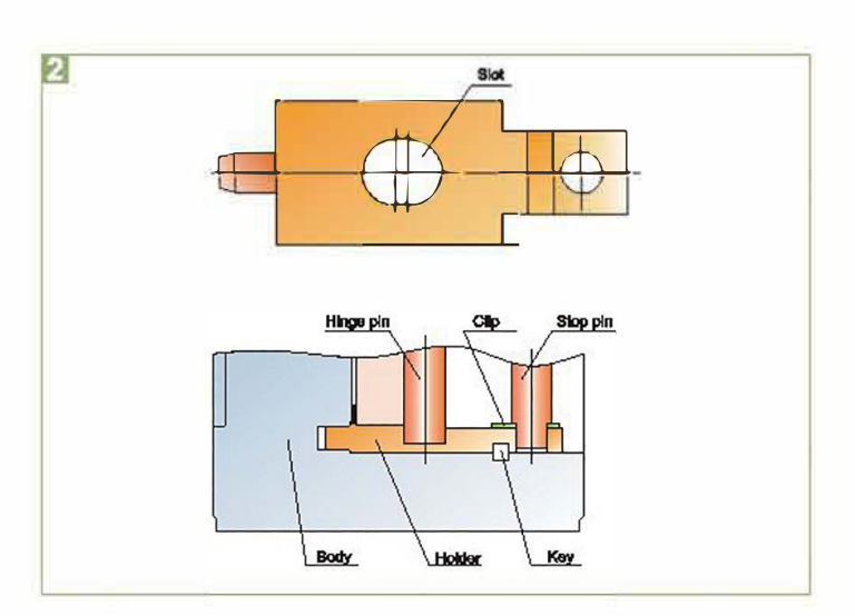
2 Body Slot Design to FI t the HInge PIn
A body slot with carefully calculated clearance is designed to fit thehinge pin and allows hinge pin to move in the only direction of flow.The design eliminates the possibility of friction caused by the heelof the dual plate.
3. Shock bumpers
The integral cast bumper on the back of the dual plate is aneffective design to prevent the frequent hitting, and reduces thepressing from the dual plate against the stop pin when the valve isfully opened, This extends the service life of the valve andminimlzies maintenance cost
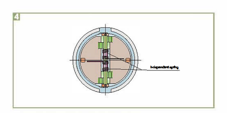
4 Two Independent Torsion Springs
Two high torsion springs ensure valve closure as quick as possible.and reduces water hammer, 90 as to extend valv e I lfe and Improvesystem performance.
5. Uninterrupted Gasket Surface
The dual plate design incorporates an internal retention fitting.The fitting does not encroach the gasket sealing surface, toensure the effective seal betwvalve and pipeline.
6. Light weight and compact w afer design
Dual plate wafer designs Inherently makes this check valve Ilghter,which is only 10~25% of the weight of conventional swing checkvalve, to saves money in initial valve cost and provides lowerinstallation cost.
7. Flexibility in Installation position
The spring feature alds In keeping the valve closed and the lighterweight in ellminating pipeline bending loads make the valve flexibleinstalled in any position, to allow you to design your piping layout inthe most efficient and least expensive method.
8. Dual plate & Flat seat design
When the valve opens, the heel of the dual plate is lifted in thedirection of the flow, to avoid that the heel drag across the seatingsurface and cause wear. When closing the valve, both the two hightorslon springs and the back pressure will force disc toe and heelback In turn to the flat seat to complete the seal.
9. Size Range
Do to features of the wafer check light weight, small Installationspace, spring alds and easy sealing, the valve may be used in thefield of lager plping slzes, even in 60″or above plping system.
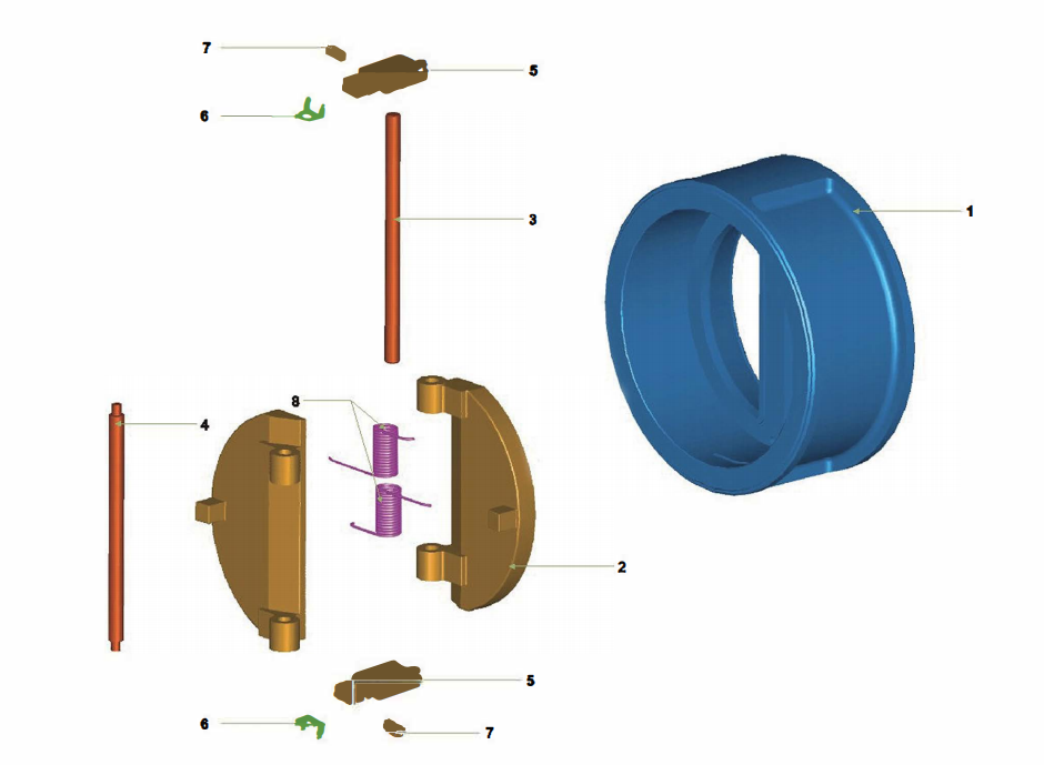
Materials
| No. | Parts | Materials | |||
|---|---|---|---|---|---|
| 1 | Body | ASTM A216-WCB/STL OVERLAY |
ASTM A352-LCC/STL OVERLAY |
ASTM A217-WC6/STL OVERLAY |
ASTM A351 CF8M/STL OVERLAY |
| 2 | Disc | ASTM A217-CA15 or ASTM A216-WCB/CR13 OVERLAY |
ASTM A351-CF8M or ASTM A352-LCC/316 OVERLAY |
ASTM A217-WC6/STL OVERLAY |
ASTMA351 CF8M |
| 3 | Hinge pin | ASTM A276-410 | ASTM A276-316 | ASTM A276-410 | ASTM A276-316 |
| 4 | Stop pin | ASTM A276-410 | ASTM A276-316 | ASTM A276-410 | ASTM A276-316 |
| 5 | Holder | ASTM A276-420 | ASTM A276-316 | ASTM A276-420 | ASTM A276-316 |
| 6 | Cilp | 3048.8 | 3168.8 | 3168.8 | 3168.8 |
| 7 | Key | ASTM A182-F304 | ASTM A182-F316 | ASTMA182-F304 | ASTMA182-F316 |
| 8 | Spring | INCONEL X-750 | INCONELX-750 | INCONELX-750 | INCONELX-750 |
| 9 | Hook screw(5⋆& larger) | Al8l 1025 | AISI 1026 | AISI 1025 | 3048.8 |
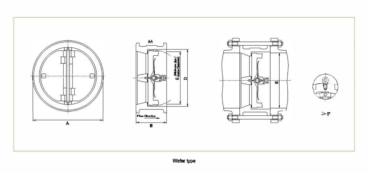
Wafer Type-ASME Class 150
| Size | Dimensions | Stud detalls | End facing |
Hook screw hole size |
Welght | ||||||||||||||
|---|---|---|---|---|---|---|---|---|---|---|---|---|---|---|---|---|---|---|---|
| A | B | D | E | No. | Dlameter | RF Stud length |
|||||||||||||
| NPS | DN | In | mm | In | mm | In | mm | In | mm | In | mm | In | mm | In | mm | lbs | kg | ||
| 2″ | 50 | 4.09 | 104 | 2.38 | 60 | 2.36 | 60 | 2.01 | 51 | 4 | 0.63 | 16 | 5.75 | 146 | RF | – | – | 6 | 3 |
| 21/2″ | 65 | 4.84 | 123 | 2.63 | 67 | 2.88 | 73 | 2.84 | 80 | 4 | 0.63 | 16 | 6.25 | 159 | RF | – | – | 11 | 5 |
| 3″ | 80 | 5.35 | 136 | 2.88 | 73 | 2.87 | 73 | 2.91 | 74 | 4 | 0.63 | 16 | 6.75 | 171 | RF | – | – | 11 | 5 |
| 4″ | 100 | 6.85 | 174 | 2.88 | 73 | 4.49 | 114 | 3.83 | 97 | 8 | 0.63 | 16 | 6.75 | 171 | RF | – | – | 18 | 8 |
| 5″ | 125 | 7.72 | 196 | 3.38 | 86 | 5.56 | 141 | 4.87 | 122 | 8 | 0.75 | 19 | 7.50 | 191 | RF | – | – | 28 | 13 |
| 6″ | 150 | 8.70 | 221 | 3.88 | 98 | 6.61 | 168 | 5.77 | 148 | 8 | 0.75 | 19 | 8.00 | 203 | RF | 0.50 | 13 | 31 | 14 |
| 8″ | 200 | 10.94 | 278 | 5.00 | 127 | 8.62 | 219 | 7.63 | 194 | 8 | 0.75 | 19 | 9.50 | 241 | RF | 0.50 | 13 | 57 | 26 |
| 10″ | 250 | 13.35 | 339 | 5.75 | 146 | 10.75 | 273 | 9.56 | 243 | 12 | 0.88 | 22 | 10.50 | 267 | RF | 0.50 | 13 | 98 | 45 |
| 12″ | 300 | 16.06 | 408 | 7.13 | 181 | 12.76 | 324 | 11.38 | 289 | 12 | 0.88 | 22 | 12.25 | 311 | RF | 0.75 | 19 | 140 | 64 |
| 14″ | 350 | 17.68 | 449 | 7.26 | 184 | 14.02 | 358 | 12.50 | 318 | 12 | 1.00 | 25 | 12.75 | 324 | RF | 0.75 | 19 | 170 | 77 |
| 16″ | 400 | 20.12 | 511 | 7.50 | 191 | 15.98 | 406 | 15.00 | 381 | 16 | 1.13 | 29 | 13.25 | 337 | RF | 1.00 | 25 | 230 | 104 |
| 18″ | 450 | 21.63 | 549 | 8.00 | 203 | 18.00 | 457 | 18.88 | 429 | 16 | 1.13 | 29 | 14.25 | 362 | RF | 1.00 | 26 | 270 | 123 |
| 20″ | 500 | 23.88 | 606 | 8.63 | 219 | 20.00 | 608 | 18.81 | 478 | 20 | 1.25 | 32 | 15.25 | 387 | RF | 1.00 | 26 | 360 | 163 |
| 24″ | 600 | 26.25 | 718 | 8.75 | 222 | 24.00 | 610 | 22.63 | 575 | 20 | 1.25 | 32 | 16.00 | 406 | RF | 1.00 | 25 | 480 | 218 |
| 28″ | 650 | 30.50 | 776 | 14.00 | 356 | 26.00 | 680 | 24.25 | 616 | 24 | 1.25 | 32 | 23.25 | 581 | RF | 1.00 | 25 | 1000 | 464 |
| 28″ | 700 | 32.75 | 832 | 15.00 | 381 | 28.00 | 711 | – | – | 28 | 1.25 | 32 | 24.50 | 622 | RF | 1.00 | 25 | 1200 | 544 |
| 30″ | 750 | 34.75 | 883 | 12.00 | 305 | 30.00 | 762 | 29.25 | 743 | 28 | 1.25 | 32 | 21.75 | 552 | RF | 1.00 | 25 | 1000 | 454 |
| 32″ | 800 | 37.00 | 940 | 14.00 | 356 | 32.00 | 813 | – | – | 28 | 1.50 | 38 | 24.75 | 629 | RF | 1.00 | 25 | 1400 | 635 |
| 36″ | 900 | 41.25 | 1048 | 14.60 | 388 | 36.00 | 914 | 35.00 | 880 | 32 | 1.50 | 38 | 28.00 | 680 | RF | 1.00 | 25 | 1750 | 794 |
| 40″ | 1000 | 45.75 | 1182 | 17.00 | 432 | 40.00 | 1016 | – | – | 36 | 1.50 | 38 | 28.50 | 724 | RF | 1.50 | 38 | 2800 | 1179 |
| 42″ | 1050 | 48.00 | 1219 | 17.00 | 432 | 42.00 | 1067 | 41.00 | 1041 | 36 | 1.50 | 38 | 29.00 | 737 | RF | 1.50 | 38 | 2850 | 1293 |
| 48″ | 1200 | 54.50 | 1384 | 20.63 | 524 | 48.00 | 1219 | 47.00 | 1194 | 44 | 1.50 | 38 | 31.00 | 787 | RF | 1.50 | 38 | 4400 | 1996 |
| 54″ | 1350 | 61.00 | 1549 | 23.25 | 501 | 54.00 | 1372 | 51.50 | 1308 | 44 | 1.75 | 44 | 35.75 | 908 | RF | 1.50 | 38 | 6500(2) | 2495(2) |
| 60″ | 1500 | 67.50 | 1715 | 28.00 | 880 | 80.00 | 1524 | 56.00 | 1422 | 52 | 1.75 | 44 | 38.75 | 984 | RF | 1.50 | 38 | 7200(2) | 3288(2) |
| Double Flanged Type-ASME Class 300 | |||||||||||||||||||
|---|---|---|---|---|---|---|---|---|---|---|---|---|---|---|---|---|---|---|---|
| Size | Dimensions | Stud detalls | End facing |
Welght | |||||||||||||||
| A | B | D | E | No. | Dlameter | RF Stud length |
|||||||||||||
| NPS | DN | In | mm | In | mm | In | mm | In | mm | In | mm | In | mm | lbs | kg | ||||
| 12″ | 300 | 20.50 | 521 | 7.13 | 181 | 12.91 | 328 | 11.38 | 289 | 16 | 1.13 | 28 | 8.75 | 171 | RF | 336 | 152 | ||
| 14″ | 350 | 23.00 | 584 | 6.75 | 222 | 14.09 | 358 | 12.50 | 318 | 20 | 1.13 | 29 | 7.00 | 178 | RF | 431 | 186 | ||
| 16″ | 400 | 25.50 | 648 | 9.13 | 232 | 16.06 | 408 | 14.31 | 384 | 20 | 1.25 | 32 | 7.50 | 191 | RF | 675 | 306 | ||
| 18″ | 450 | 28.00 | 711 | 10.38 | 264 | 18.00 | 457 | 16.68 | 429 | 24 | 1.26 | 32 | 7.75 | 187 | RF | 850 | 388 | ||
| 20″ | 500 | 30.50 | 775 | 11.50 | 292 | 20.00 | 508 | 17.94 | 456 | 24 | 1.25 | 32 | 8.26 | 210 | RF | 1078 | 489 | ||
| 24″ | 500 | 36.00 | 814 | 12.30 | 318 | 24.00 | 610 | 21.56 | 548 | 24 | 1.50 | 38 | 9.25 | 235 | RF | 1965 | 891 | ||
| 28″ | 850 | 38.26 | 972 | 14.00 | 356 | 28.00 | 660 | 24.38 | 619 | 28 | 1.63 | 41 | 10.50 | 267 | RF | 2200 | 998 | ||
| 28″ | 700 | 40.75 | 1035 | 15.00 | 361 | 28.00 | 711 | – | – | 28 | 1.63 | 41 | 11.00 | 279 | RF | 2600 | 1179 | ||
| 30″ | 750 | 43.00 | 1092 | 14.50 | 368 | 30.00 | 762 | 28.75 | 730 | 28 | 1.75 | 44 | 11.75 | 298 | RF | 3526 | 1599 | ||
| 32″ | 800 | 45.26 | 1149 | 16.00 | 408 | 32.00 | 813 | – | – | 28 | 1.88 | 48 | 12.75 | 324 | RF | 3300 | 1497 | ||
| 38″ | 800 | 50.00 | 1270 | 19.00 | 483 | 36.00 | 914 | 35.00 | 889 | 32 | 2.00 | 51 | 13.25 | 337 | RF | 4700 | 2132 | ||
| 40″ | 1000 | 58.75 | 1238 | 21.50 | 548 | 36.00 | 914 | – | – | 32 | 1.63 | 41 | 13.25 | 337 | RF | 4900 | 2223 | ||
| 42″ | 1050 | 50.75 | 1289 | 22.38 | 568 | 40.00 | 1016 | 41.00 | 1041 | 32 | 1.63 | 41 | 13.75 | 349 | RF | 5000 | 2268 | ||
| 48″ | 1200 | 57.75 | 1467 | 24.75 | 628 | 44.00 | 1118 | 47.00 | 1194 | 32 | 1.88 | 48 | 15.25 | 387 | RF | 7400 | 3357 | ||
| Double Flanged Type-ASME Class 600 | |||||||||||||||||||
| Size | Dimensions | Stud details | End facing | Welght | |||||||||||||||
| A | B | D | E | No. | Dlameter | RF Stud length |
RFJ Stud length |
||||||||||||
| NPS | DN | In | mm | In | mm | In | mm | In | mm | In | mm | In | mm | In | mm | lbs | kg | ||
| 12″ | 300 | 22.00 | 669 | 9.00 | 229 | 12.76 | 324 | 11.38 | 289 | 20 | 1.26 | 32 | 8.50 | 216 | 9.00 | 229 | RF/RTJ#67 | 660 | 249 |
| 14″ | 350 | 23.75 | 603 | 10.75 | 273 | 14.00 | 358 | 12.50 | 318 | 20 | 1.38 | 35 | 9.0)0 | 229 | 9.50 | 241 | RF/RTJ#61 | 846 | 384 |
| 16″ | 400 | 27.00 | 688 | 12.00 | 306 | 18.00 | 406 | 14.31 | 384 | 20 | 1.60 | 38 | 9.76 | 248 | 10.26 | 260 | RF/RTJ#66 | 1010 | 468 |
| 18″ | 450 | 29.25 | 743 | 14.25 | 382 | 18.00 | 457 | 18.13 | 410 | 20 | 1.83 | 41 | 10.50 | 267 | 11.00 | 279 | RF/RTJ#69 | 1320 | 599 |
| 20″ | 600 | 32.00 | 813 | 14.60 | 368 | 20.00 | 608 | 17.94 | 466 | 24 | 1.83 | 41 | 11.26 | 286 | 11.76 | 298 | RF/RTJ#73 | 1700 | 771 |
| 24″ | 600 | 37.00 | 940 | 17.25 | 438 | 24.00 | 810 | 21.56 | 548 | 24 | 1.83 | 41 | 12.25 | 311 | 13.00 | 330 | RF/RTJ#77 | 2580 | 1170 |
| 26″ | 660 | 40.00 | 1016 | 18.00 | 457 | 25.00 | 660 | 24.00 | 610 | 28 | 1.88 | 48 | 13.26 | 337 | 14.26 | 382 | RF/RTJ#93 | 3100 | 1406 |
| 28″ | 700 | 42.25 | 1073 | 19.00 | 483 | 28.00 | 711 | – | – | 28 | 2.00 | 51 | 14.00 | 358 | 15.00 | 381 | RF/RTJ#94 | 3800 | 1724 |
| 30″ | 750 | 44.50 | 1130 | 19.88 | 505 | 30.00 | 762 | 28.75 | 730 | 28 | 2.00 | 51 | 14.00 | 356 | 15.00 | 381 | RF/RTJ#95 | 5390 | 2445 |
| 32″ | 800 | 47.00 | 1194 | 21.00 | 533 | 32.00 | 813 | – | – | 28 | 2.25 | 57 | 14.75 | 375 | 16.00 | 408 | RF/RTJ#98 | 6000 | 2722 |
| 36″ | 900 | 61.75 | 1314 | 26.00 | 835 | 38.00 | 914 | 33.75 | 867 | 28 | 2.50 | 64 | 16.00 | 406 | 17.00 | 432 | RF/RTJ#98 | 6700 | 3039 |
| 42″ | 1050 | 55.25 | 1403 | 27.60 | 701 | 38.00 | 965 | 39.50 | 1003 | 28 | 2.50 | 64 | 19.50 | 495 | – | – | RF | 9400 | 4264 |
| Double Flanged Type-ASME Class 900 | |||||||||||||||||||
| Size | Dimensions | Stud details | End facing | Weight | |||||||||||||||
| A | B | D | E | No. | Dlameter | RF Stud length |
RFJ Stud length |
||||||||||||
| NPS | DN | In | mm | In | mm | In | mm | In | mm | In | mm | In | mm | In | mm | lbs | kg | ||
| 12″ | 300 | 24.00 | 610 | 11.50 | 292 | 12.75 | 324 | 10.13 | 257 | 20 | 1.38 | 35 | 8.75 | 222 | 9.25 | 235 | RF/RTJ#57 | 770 | 349 |
| 14″ | 350 | 25.25 | 641 | 14.00 | 356 | 14.00 | 356 | 11.50 | 282 | 20 | 1.50 | 38 | 9.25 | 235 | 10.00 | 254 | RF/RTJ#62 | 1240 | 562 |
| 16″ | 400 | 27.75 | 705 | 15.13 | 384 | 16.00 | 406 | 12.81 | 325 | 20 | 1.63 | 41 | 10.00 | 254 | 10.75 | 273 | RF/RTJ#68 | 1210 | 549 |
| 18″ | 450 | 31.00 | 787 | 17.75 | 451 | 18.00 | 457 | 14.44 | 367 | 20 | 1.88 | 48 | 11.00 | 279 | 11.75 | 298 | RF/RTJ#70 | 1845 | 837 |
| 20″ | 500 | 33.75 | 857 | 17.75 | 451 | 20.00 | 508 | 17.94 | 456 | 20 | 2.00 | 51 | 12.00 | 305 | 12.75 | 324 | RF/RTJ#74 | 3940 | 1787 |
| 24″ | 800 | 41.00 | 1041 | 19.50 | 495 | 24.00 | 810 | 21.50 | 546 | 20 | 2.50 | 64 | 14.00 | 358 | 15.00 | 381 | RF/RTJ#78 | 4175 | 1884 |
| Note: 1. A=OD 2. B=Fto F 3.D=ID 4.E=Minimum ID 6. Yellow part is amened by technical Dept. 8. Above data are origined from Vetan cataloge VEL-PQCV-2006 |
|||||||||||||||||||