sales@lokvalve.com
What are the classifications of ball valves
 secureluokai
 September 30, 2026

Ball valves are widely used to control the flow of liquids and gases in pipelines. They operate by rotating a ball with a passage through it: when the passage aligns with the pipe, fluid can flow; when the ball turns approximately 90 degrees, the valve closes. Their quick operation, compact design, and reliable shutoff make them common in water systems, chemical processing, oil and gas facilities, and industrial equipment. However, ball valves are not all built for the same conditions. They can be classified by how the ball is supported, the size and shape of the flow passage, the construction of the body, the seat material, and the method of operation. These categories overlap, so a single valve may belong to several classifications at once. Understanding the differences helps buyers select a valve that suits the operating pressure, temperature, fluid characteristics, and maintenance requirements.
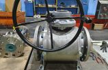
One fundamental classification is the distinction between floating ball valves and trunnion mounted ball valves. In a floating ball valve, the ball is connected to the stem but is not rigidly supported against movement in the direction of flow. Fluid pressure can push it slightly against the downstream seat, helping form a tight seal. This relatively simple construction is widely used in smaller sizes and in services where pressure, temperature, and operating torque remain within the design limits. As valve size and differential pressure increase, the force acting on the seats can make operation more demanding. A trunnion mounted ball valve supports the ball at the top and bottom, restricting its displacement. The seats are typically designed to move toward the ball, with springs and fluid pressure helping maintain sealing contact. This arrangement can reduce operating torque and is often chosen for larger pipelines and higher pressure applications. Neither design is universally superior; the appropriate choice depends on the valve’s rated capability and the actual service conditions.
Ball valves are also classified by their flow passage and port arrangement. Full bore, or full port, valves have an opening approximately equal to the internal diameter of the connecting pipe, subject to the applicable design standard. They offer low flow resistance and are useful where pressure loss must be minimized. Full bore construction is also generally necessary for pipelines that require pigging, although the entire valve geometry must be compatible with the intended pig. Reduced bore valves have a smaller opening than the connecting pipe. They are often lighter and less expensive, but their narrower passage creates greater flow resistance. For flow regulation, V-port designs use a V-shaped opening in the ball or seat to provide a more controlled change in flow area as the valve rotates. Such valves can be suitable for throttling when properly sized and engineered for the service; ordinary shutoff ball valves should not automatically be treated as control valves. Port arrangement provides another distinction. Two-way valves control a single flow path, while three-way valves commonly use L-shaped or T-shaped passages to divert, select, or combine flows. The available flow patterns depend on the internal design and permitted operating positions.
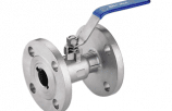
Body construction provides another practical way to classify ball valves because it affects installation and maintenance. One-piece valves have a main body formed as a single piece and commonly offer a compact, economical solution, although access to internal parts is often limited. Two-piece valves use two main body sections and are widely selected for general industrial service. Depending on their connections and installation, they may need to be removed from the pipeline for internal maintenance. Three-piece valves typically have a central body section positioned between two end sections. Many designs allow the central section to be removed or swung out for servicing while the pipe connections remain in place, provided adequate clearance is available. Ball valves may also be described as side entry or top entry. Side entry designs are assembled through body sections, while top entry designs allow access to the ball and seats through an upper cover. Top entry construction can support maintenance with the body still installed, but the valve must first be safely isolated and depressurized. Threaded, flanged, socket weld, and butt weld connections are further classifications that influence installation methods and ease of removal.
Seat material and actuation complete the main classification picture. Soft seated ball valves use materials such as PTFE, reinforced PTFE, or other suitable polymers to achieve tight shutoff. Their allowable temperature, pressure, and chemical exposure depend on the specific material and valve design. Metal seated ball valves use metallic sealing surfaces, often with specialized coatings or hardening treatments, and can be appropriate for higher temperatures or abrasive service. Their leakage performance must be checked against the specified testing standard rather than assumed from the seat type alone. In terms of actuation, manual valves use a lever or gearbox, while automated valves use pneumatic, electric, or hydraulic actuators. Pneumatic actuators are common where compressed air is available, electric actuators suit many remote control applications, and hydraulic actuators can provide substantial torque. Any required response to loss of power or control pressure must be specified separately. When comparing products, buyers should describe the complete configuration—for example, a full bore, trunnion mounted, soft seated valve with pneumatic actuation—and verify its pressure rating, temperature limits, material compatibility, and shutoff requirements against the intended operating conditions.
If you have any questions or inquiries, please feel free to contact us with sales@lokvalve.com or WhatsApp: +8618616568786